Conveying Solutions
CALL US TODAY:
(800) 684-2358
- About
- Products
- Fabrication
- Services & Repairs
- Industries
- Resources
- Contact
- Belt Power Site
Conveyor belts are frequently blamed for belt tracking problems and in most cases this is unjustified. The failure cause is usually to be found in the installation itself and may be the result of poorly adjusted pulleys and rollers, incorrect application of belt tracking measures or faulty design. It is therefore essential to be fully aware of the basic characteristics of the different belt tracking measures and for these to be employed correctly.
A distinction needs to be made between basic and additional measures for belt tracking. The former are appropriate for maintaining a correctly aligned belt in its central position as long as no great external influences are exerted on the belt, such as transverse forces. The latter are necessary when the basic measures alone are either insufficient or inappropriate to control belt tracking sufficiently.
Regardless which measures are taken, the following conditions are essential for problem-free belt tracking:
What happens if a conveyor has no tracking measure at all?
Where a belt runs over cylindrical pulleys that are at right angles to its directional path, then the forces acting upon it will be parallel to the running direction of the belt. No tracking forces are exerted on the belt.
In fact, the belt is running in a state of unstable equilibrium and would run off immediately if subjected to the slightest external factors such as off-center loading of product, dirt between belt and pulley, belt distortion or lateral feeding or diverting of goods.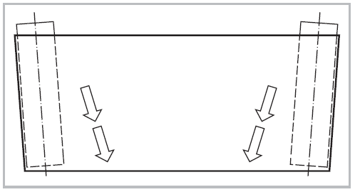
The same scenario applies if one or both of the two pulleys are not positioned accurately at right angles to the belt running axis. The belt will inevitably run off towards the less-tensioned side.
The belt tracks to the side with the least tension.
Fabric belt conveyors are normally equipped with at least one, sometimes with several pulleys with cylindrical conical or radially crowned form. This basic measure is usually sufficient to achieve straight and stable running.
 Pulleys with this shape exert a self-tracking effect. If there is a variable run-off tendency, or a reversal in running direction, the belt is centered without the need to adjust the axis. Detailed information on cylindrical conical pulleys
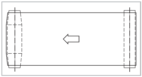
In simple two-pulley conveyors with defined running direction it is usually the head pulley that is the driving pulley. It is designed in cylindrical-conical shape.
With conveyor aspect ratio (conveyor length to belt width) in excess of about 5 to 1 and in installations with reversing operations, it is advisable to crown both, head pulley and tail pulley.
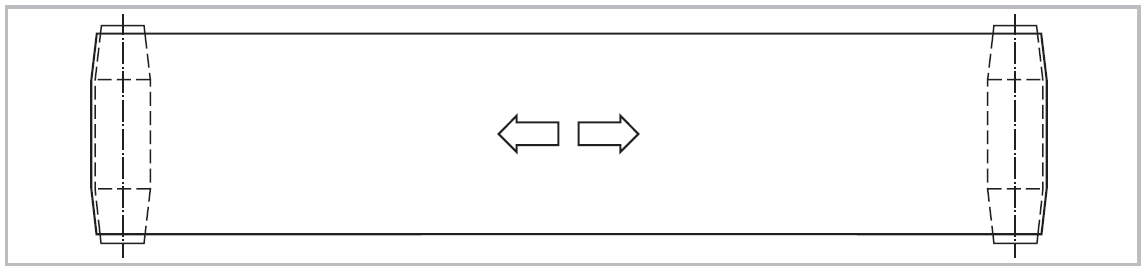
Following this method, a correctly aligned belt can be maintained in its central position as long as there is no excessive deflection of the pulleys.
Additional belt tracking measures:
On installations with a pronounced run-off tendency and considerable transverse forces (side feed, diverter bar, a lot of redirection in the belt path, etc.), the basic use of cylindrical-conical pulleys, will not be sufficient. Additional belt tracking measures will be required, but these will be determined by application and operating conditions.
Guiding pulleys, also called control pulleys, are adjustable snub pulleys.
Guiding pulleys are usually cylindrical. Observe the minimum diameter for counterflections according to the indication in the product data sheets. To achieve good tracking, the arc of contact at the guiding pulley should be minimum 30°. For belts with non-adhesive surface, the tracking effect can be improved with a friction cover of abrasion-resistant rubber or synthetic material (recommended hardness 80 – 90 Shore A).
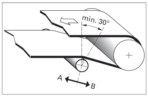
The larger the arc of contact and the higher the friction, the greater the tracking effect. To keep the belt tension as low as possible, the pivoting movement should, wherever possible, be perpendicular to the median line of the arc of contact (plane A ↔ B). The center distance between the end pulley and guiding pulley should be at least twice the diameter of the larger pulley. Unlike cylindrical-conical pulleys, adjustable cylindrical rollers are not self-tracking. This means when belt running direction changes, the pivoted position of cylindrical pulleys must be reset. As this is not practicable, the use of adjustable cylindrical rollers for belt tracking is not recommended for reversing operation. However, exception to this rule can be made for long conveyors. Provided there is sufficient distance between the guiding pulleys, they can be used even for reversing operations as well.
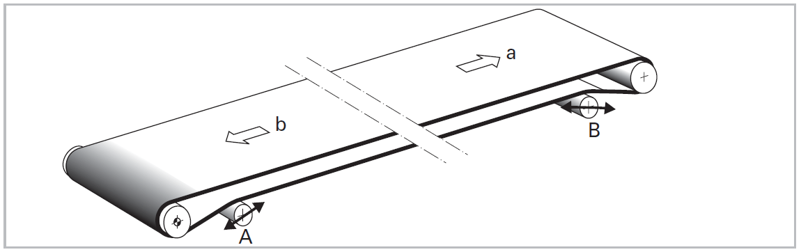
Guiding pulley A tracks the belt correctly in running direction a, guiding pulley B tracks the belt correctly in running direction b.
In group of pulleys and rollers the one that the belt first makes contact with has the larger tracking effect (in the adjacent example roller A).
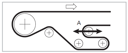
The tracking effect of inclined rollers on the return side is maximized if they are fitted to the running-on side in front of the tail pulley for head drive and in front of the driving pulley for tail drive.
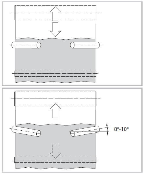
The positioning of rollers under the belt, i.e. on the conveying side of the belt, produces a good tracking effect due to the higher coefficient of friction, however, possible tracking marks on the belt cover must also be taken into consideration.
The rollers can also be positioned above the belt on its running side. This is desirable in cases where the belt has a delicate or highly structured conveying side, or has transversely mounted profiles.
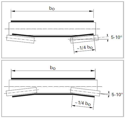
To achieve a satisfactory tracking effect, the belt contact of a roller should be around ¼ of the belt width and the rollers angle of incline should be 5° to 10°.
If the inclined rollers are fitted exactly at right angles to the belt running direction, the belt will automatically correct its own position should a change in run-off tendency occur.
This measure works also in reversing operation.
Belt tracking is further improved when the inclined rollers are angled forward by 8° to 10° at the belt edges in the running direction of the belt. Their effect can be enhanced by adding a friction cover.
However, rollers angled forward shall not be used for reversing operation as the belt centering forces are thereby reversed as well.
Inclined rollers on the return side have also proven successful for tracking wide, short belts and with thin belts at high speeds. In this case driving pulleys and tail pulleys are to be fitted with cylindrical profiles in order to avoid folding or creasing.
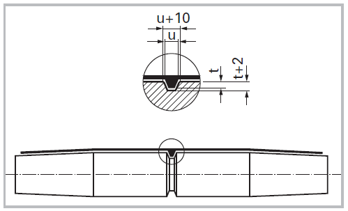
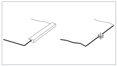
Guiding profiles are usually V-shaped, welded or glued onto the running side of the conveyor belt. Rectangular and semicircular profiles are also used at times.
Because of the relatively high production costs and their limited effectiveness, guiding profiles are not recommended as a general belt tracking measure. Particularly not suitable are guiding profiles in applications with high speed, as they have a tendency to be forced out of the groove allowing the belt to continue to run off.
Guiding profiles are well suited for offsetting localized transverse forces. In this context the term “transverse forces” refers to those forces exerted briefly on the side of the conveyor belt, for instance during side loading or diverting.
In principle, the belt must be tracked by common measures, usually by cylindrical-conical pulleys. Only in the zone where the transverse forces occur, the guiding profile has to prevent the belt from running off.
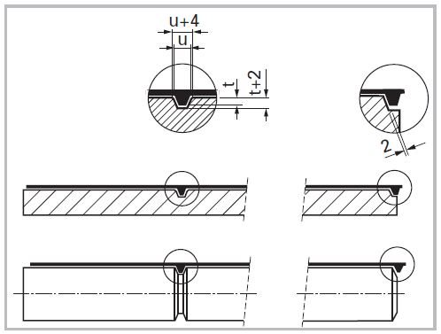
This means, the groove dimensions should have different sizes:
A. In locations where no lateral forces occur, the grooves should be wide, that is around 8 to 10 mm / 0.31 to 0.39 in wider than the guiding profile. The greater clearance permits the adjustment of the belt without the guiding profiles permanently running against the sides of the grooves.
This is particularly true for the drive, head and tail pulleys.
An exception of this general rule has to be considered for guiding profiles in short, but wide conveyors. In this case it is advisable to make the grooves in the pulleys narrower than those in the slider bed.
B. In the zone where the transverse force occurs, that is to say on the slider bed or on the carrying rollers, the grooves should be narrow, i.e. only around 4 mm / 0.16 in wider than the guiding profile.
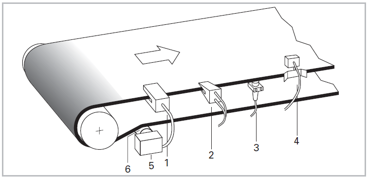
Automatic belt control can solve even the most serious belt tracking problems. However, it is a comparatively expensive option and, therefore, used where belt tracking behavior is either highly critical and/or where other belt tracking methods have proven ineffective i.e., chronic build up contaminating rollers/pulleys.
Automatic belt control works by sensing the edges of the belt, either by means of noncontact sensors or by mechanical means. The signal is sent to a control mechanism, which actuates a guiding pulley, which accurately centers the belt.
It is advisable to make the tail pulley cylindrical. With a cylindrical-conical tail pulley a conflict between the two regulation systems would possibly result in a quite disturbed belt run.
It is recommended that one side of the guide/control roller is equipped with a standard adjustment device so that the tracker assembly can be initially aligned manually. While this is being done, the automatic control should be in the neutral position.
A number of companies supply automatic belt tracker products and we recommend that where an installation demands these devices that specialist advice is taken.
In addition to the belt tracking measures previously described, there are other options that can be used depending on certain preconditions and on type of application. The advantages and disadvantages of a number of these alternatives are detailed below.
 In areas where local transverse forces occur, tracked belts will be kept in place by additional belt wraps. The effect can be enhanced by covering the additional pulleys.
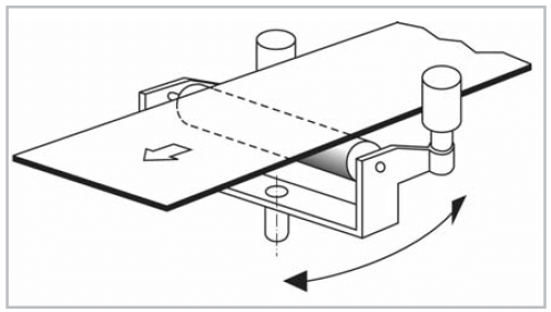
Running-off belts can be tracked by adjustable rollers. Horizontal adjustment (A) is suitable for one running direction only.
Vertical adjustment (B) will also track the belt for reversing operation.
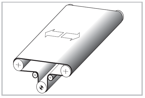
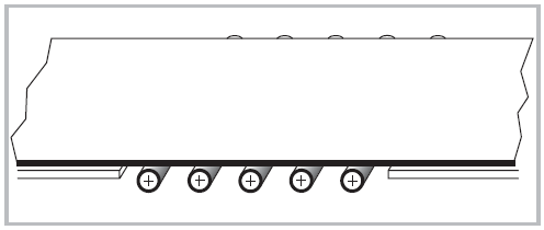 Local transverse forces can also be dealt with by installing multiple carrying rollers with friction cover. This method is suitable both for installations with slider bed and carrying rollers. With rollers adjusted exactly perpendicular to the belt running direction, the tracking will also work for reversing operation.
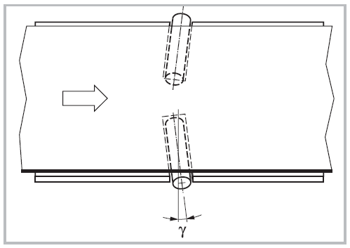
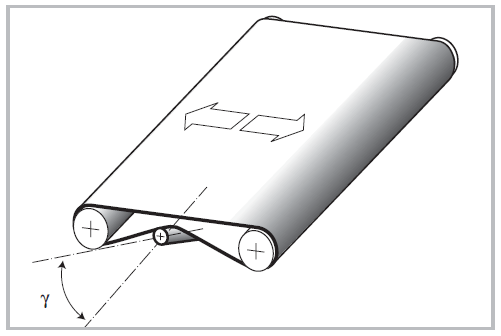
Cylindrical rollers are installed at the belt edges and angled forward in the belt running direction. The skew angle, γ, should be 3° to 12° depending upon belt load, the friction between roller and belt, and on the belt speed.
This method is not recommended to be used with thin belts of low transverse rigidity. Since the belt does not only run on the rollers but also slides, friction exists and thus increases belt wear. This tracking method centers the belt only in the running direction. This method is only effective for centrally located and uniformly distributed conveying goods.
 This tracking device is used for heavy belts and for belts with high lateral stability. Specialty manufacturers supply these units, which can also be equipped with adjustable sensors that substantially reduce belt edge wear.
This tracking method works only in one running direction.
 This tracking measure is only possible for belts with sufficient lateral rigidity and edge integrity, however, belt edge wear will increase. Guide rollers are preferable to lateral wear strips in this respect.
The tracking measure will also work for reversing operation.
Edge guide strips are best suited for relatively clean conveying operations as debris may become lodged between the belt and guide strip causing significant belt damage and other performance problems.
The entrance of edge guide strips must be radiused in order to minimize potential edge damage.
The belt edges can be abrasive themselves. It is advisable, therefore, to consider using durable low friction materials for edge guide strips i.e., stainless steel, phenolic (such as Delrin) etc.
Conveyor belts on installations, where the belt width is equal or larger than the conveying length, are increasingly difficult to guide. Namely thin belts with little lateral stiffness, particularly at high speed, have a tendency to buckle and potentially fold over when fitted on short conveying distances with cylindrical-conical pulleys. Accurate Industrial recommends that the head and tail pulleys should be cylindrical and must be installed absolutely parallel and square to the belt running direction.
Further measures, as recommended in the following, should be considered to ensure effective belt guidance in these cases.
 Advisable for guiding wide belts with short conveying distances are inclined rollers on the return side.
To achieve a satisfactory tracking effect the roller inclination γ, should be at minimum 5° to 10° in some cases up to 45°. This configuration provides for a self centering effect of the belt.
Provided the rollers are fitted at right angles to the belt running direction, the measure is also effective with reversing operations.
 Center drive is recommended for reversing operation. The driving pulley should be cylindrical-conical and, if required, lagged. Head and tail pulley as well as deflection rollers are of cylindrical shape.
For slow belt speed the head and/or tail pulleys can be cylindrical-conical shaped.
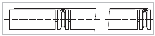
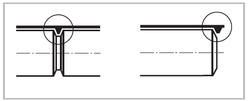 Short, wide belts can be guided effectively by using guiding profiles, provided there is sufficient belt transverse rigidity and fairly low speed. It is advisable to guide the belt in the pulleys rather than in the slider bed. This means, the grooves in the pulleys should be narrower than those in the slider bed.
Grooved rollers must be large enough to offset the added deflection created by the small diameter of the roller at the base of the groove. By moving the groove to the edge of the roller, deflection is significantly reduced. As a result, it may be possible to use a smaller diameter roller without creating excessive deflection (minimum pulley diameter of guide must be considered).
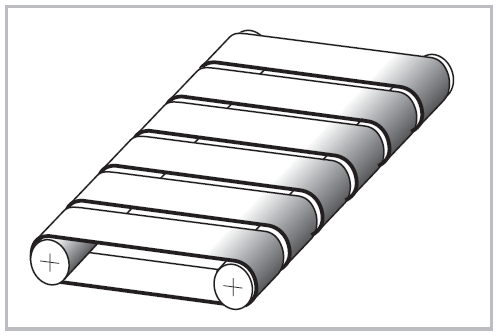 In cases where the application does not require a wide belt, the use of several narrow belts is recommended. The tracking can be controlled much easier.
Note: Each belt has to be guided and tensioned separately, unless elastic belts are used.
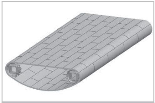 For short and wide conveyors, plastic modular belts are common alternative to traditional fabric belts. Plastic modular belts are sprocket driven, and thereby positively located by the fixed position of a drive sprocket. For the design of modular belts, the conveyor’s special requirements must be taken into account.
As a basic measure it is recommended to equip at least one, sometimes several pulleys with cylindrical-conical or crowned shape. If this basic measure is not sufficient to achieve straight and stable running, additional tracking measures need to be considered.